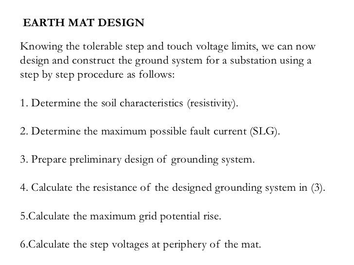
Earth Mat Design Calculation
Https Www Ijareeie Com Upload 2018 April 14 Eee2 Pdf

Earth Mat Calculations Electrical Resistivity And Conductivity Electrical Engineering
Ac Grounding Requirements Calculator Spreadsheet Engineers Edge Www Engineersedge Com
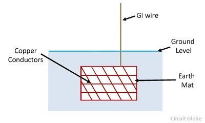
Procedure Methods Of Earthing Circuit Globe
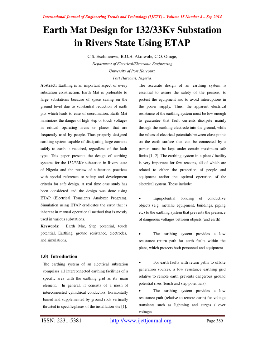
Pdf Earth Mat Design For 132 33kv Substation In Rivers State Using Etap
Earth Mat Design For Metro Station

Maximum symmetrical fault current.
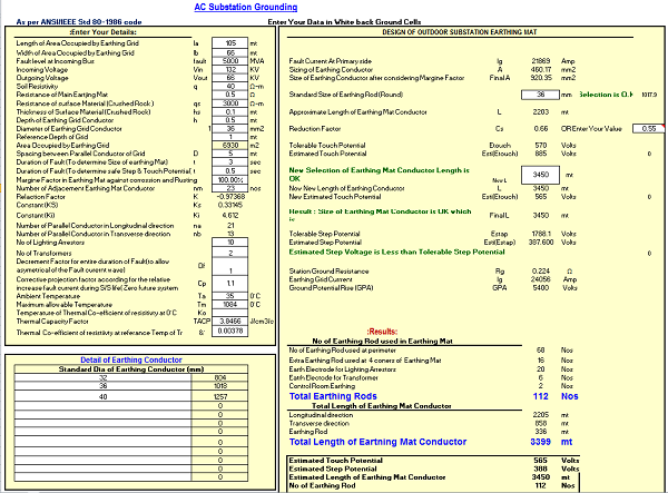
Earth mat design calculation. The grounding system in substation is very important. In our analysis we have considered an area of 275m x 175m. The average soil resistivity measured as. Today we are going to discuss the design of substation earthing system.
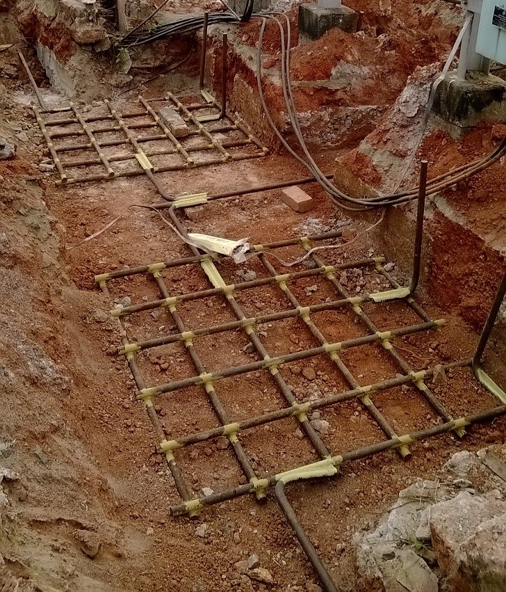
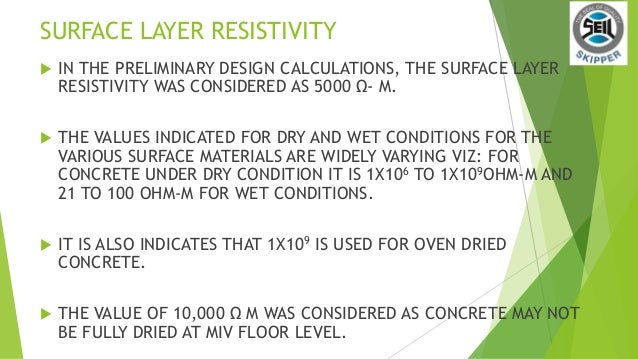
Earth mat design for 132kv substation in rivers state using etap pdf. It is suggested that the use of a high resistivity surface layer is capable of improving the safety while designing substation earthing grid in high resistivity. Difference between grounding earthing and bonding. The substation earthing system comprises of a grid earth mat formed by a horizontal buried conductors.
Can t do the earth mat design separately for each step and finally connect each steps together. It will have a considerable impact on grid resistance. Earth mat design calculation for 33 kv s stn for m s sukhbir agro energy ltd shahjahanpur u p. The cross section of the buried cable should calculated in accordance with the value of the phase to earth short circuit current but it is common to use the three phase short circuit current for this purpose.
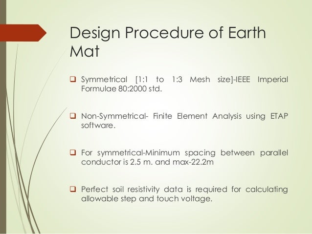
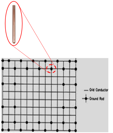
The earthing grid can dis sipate the fault currents so. Is to be considered as 1 sec. Important formulas for designing a substation grid earthing system. We have already given an introduction to substation earthing system in an article published earlier.
Design calculation are based on ieee80 2000. Could u please explain me how to do the earth mat design for 220 132 33 kv outdoor gss which have 5 steps 135m 138m 141m 144m 147m. Before 1960s the design criterion of substation earthing system was low earth resistance earth resistance 0 5 ohms for high voltage installations. We use safegrid earthing software for the design of earth grid on complex renewable energy projects including anaerobic digestion plants wind farms and solar farms.
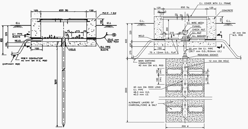
For earth mat design for hv s stn. Read about design of substation earthing system here. Duration of fault.

Design Of Earthing System For Hv Ehv Ac Substation A Case Study Of 400kv Substation At Aurangabad India Semantic Scholar

How To Design Earthing System In Substation

Our Reading Of Earth Resistivity Is Coming Avarage 2800 Ohm Meter We Are Designing 11 33 Kv Co Generation Substation What Are The Next Steps Required For Designing Earth Mat For 70 X
Https Www Ijert Org Research Design Of Earth Grid For A 3311kv Gis Substation At A High Soil Resistivity Site Using Cymgrd Software Ijertv3is101000 Pdf
Why Earthing Is Important In Substation
Department Of Eee Adbu Eee World Design Of Grounding Earthing System In A Substation Grid
Design Of Earthing System For Extra High Voltage Ac Power Substations Eep

Earth Mats Copper Lattice Earthing Mats Earthing Substation Mat Hv

Earth Mat Design 33 11kv Ss Pdf Electrical Engineering Physical Quantities

Pdf Design Of Grounding System For Substation International Journal Of Trend In Scientific Research And Development Ijtsrd Academia Edu
Easypower Webinar An Introduction To Grounding Calculations And Why They Are Necessary V714
Pdf Grid Grounding Calculations For A 132 Kv Substation Using Soil Backfilling

Pdf Design Of Groundmat For 11kv Substation Using Auto Grid Pro

Guideline For Earthing Of Buildings And Industrial Plants
Ground Grid Systems Software Ground Grid Design Ieee 80 Ieee 665

4 Etap Ground Grid System Module Youtube
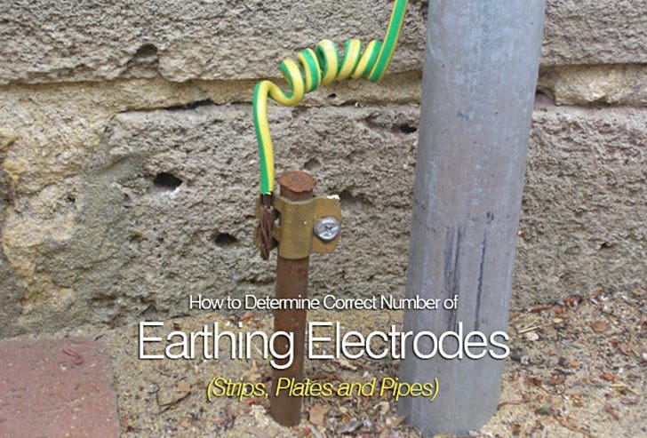
How To Determine Correct Number Of Earthing Electrodes Strips Plates And Pipes Part 1
Tiga Earth Mat Presentation
Https Encrypted Tbn0 Gstatic Com Images Q Tbn 3aand9gcr Rut7qaokxq1lribz8bxdwood9xnvz Cobncb4kgmjaicyzgn Usqp Cau

Calculation Of Touch Voltage And Ground Current
Importance Of An Adequate Substation Ground Grid Design 3 Phase Associates
Electrical Test Equipment Power Station To Plug Megger

Earth Mat In Substation Youtube
Earthing System Calculation For 132 11 Kv 1 40 Mva Substation Of Steel Factory Eep
Http Www Delhimetrorail Com Tender Otherdocuments Dmes0025 Pdf

Pdf Effects Of High Fault Currents On Ground Grid Design
Https Ieeexplore Ieee Org Iel7 6287639 8600701 08740849 Pdf
Http Www Ijeert Org Pdf V3 I4 4 Pdf
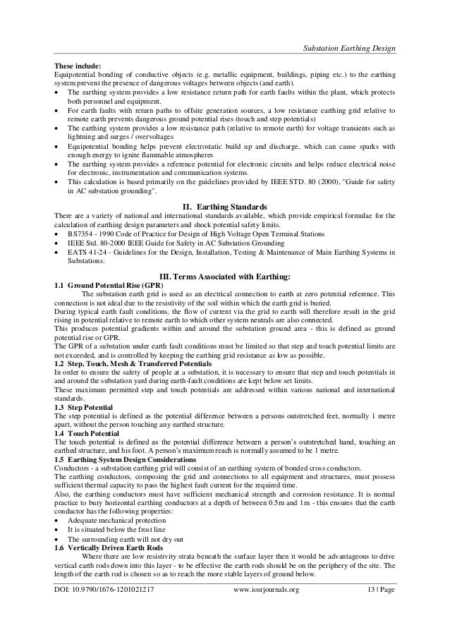
Substation Earthing Design

Measurements And Calculations Of Earth Electrode Systems Bs 7430 Eep
Http Www Iitk Ac In Npsc Papers Npsc2018 1570459039 Pdf
Ecng 3015 System Earthing

Electrical Earthing Design Uk Cdegs Greymatters Global

Earth Electrode Testing Youtube
Https Www Ijareeie Com Upload 2016 October 15 Optimal Pdf
Electrical Ms Excel Spreadsheets
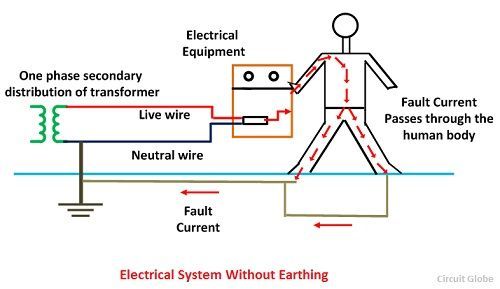
What Is Electrical Earthing Definition Types Of Earthing Its Importance In Electrical System Circuit Globe
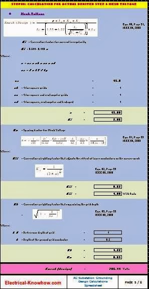
Grounding Design Calculations Part Seventeen Electrical Knowhow

Lightning Surge Protection And Earthing Of Electrical Electronic Systems In Industrial Networks
Http Www Iitk Ac In Npsc Papers Npsc2002 150 Pdf

Design Electrical Earthing Or Grounding Grid Using Etap For Power System Engineering Courses Youtube

Design And Analysis Of Ground Grid System For Substation Using E Tap Software And Fdm Code In Matlab Ijert

